Sunday, October 24, 2010

LTE Layer 1 Services

Multiple Access
The multiple access scheme for the LTE physical layer is based on Orthogonal Frequency Division Multiplexing (OFDM) with a cyclic prefix (CP) in the downlink, and on Single-Carrier Frequency Division Multiple Access (SC-FDMA) with a cyclic prefix in the uplink. To support transmission in paired and unpaired spectrum, two duplex modes are supported: Frequency Division Duplex (FDD), supporting full duplex and half duplex operation, and Time Division Duplex (TDD).

The Layer 1 is defined in a bandwidth agnostic way based on resource blocks, allowing the LTE Layer 1 to adapt to various spectrum allocations. A resource block spans either 12 sub-carriers with a sub-carrier bandwidth of 15kHz or 24 sub-carriers with a sub-carrier bandwidth of 7.5kHz each over a slot duration of 0.5ms.

The radio frame structure type 1 is used for FDD (for both full duplex and half duplex operation) and has a duration of 10ms and consists of 20 slots with a slot duration of 0.5ms. Two adjacent slots form one sub-frame of length 1ms. The radio frame structure type 2 is used for TDD and consists of two half-frames with a duration of 5ms each and containing each 8 slots of length 0.5ms and three special fields (DwPTS, GP and UpPTS) which have configurable individual lengths and a total length of 1ms.

A sub-frame consists of two adjacent slots, except for sub-frames 1 and 6, which consist of DwPTS, GP and UpPTS. Both 5ms and 10ms switch-point periodicity are supported.

To support a Multimedia Broadcast and Multicast Service (MBMS), LTE offers the possibility to transmit Multicast/Broadcast over a Single Frequency Network (MBSFN), where a time-synchronized common waveform is transmitted from multiple cells for a given duration. MBSFN transmission enables highly efficient MBMS, allowing for over-the-air combining of multi-cell transmissions in the UE, where the cyclic prefix is utilized to cover the difference in the propagation delays, which makes the MBSFN transmission appear to the UE as a transmission from a single large cell. Transmission on a dedicated carrier for MBSFN with the possibility to use a longer CP with a sub-carrier bandwidth of 7.5kHz is supported as well as transmission of MBSFN on a carrier with both MBMS transmissions and point-to-point transmissions using time division multiplexing.

Transmission with multiple input and multiple output antennas (MIMO) are supported with configurations in the downlink with two or four transmit antennas and two or four receive antennas, which allow for multi-layer transmissions with up to four streams. Multi-user MIMO i.e. allocation of different streams to different users is supported in both UL and DL.

Physical channels and modulation

The physical channels defined in the downlink are:
• the Physical Downlink Shared Channel (PDSCH),
• the Physical Multicast Channel (PMCH),
• the Physical Downlink Control Channel (PDCCH),
• the Physical Broadcast Channel (PBCH),
• the Physical Control Format Indicator Channel (PCFICH)
• and the Physical Hybrid ARQ Indicator Channel (PHICH).

The physical channels defined in the uplink are:
• the Physical Random Access Channel (PRACH),
• the Physical Uplink Shared Channel (PUSCH),
• and the Physical Uplink Control Channel (PUCCH).

In addition, signals are defined as reference signals, primary and secondary synchronization signals. The modulation schemes supported in the downlink and uplink are QPSK, 16QAM and 64QAM.

Channel coding and interleaving
The channel coding scheme for transport blocks in LTE is Turbo Coding with a coding rate of R=1/3, two 8-state constituent encoders and a contention-free quadratic permutation polynomial (QPP) turbo code internal interleaver. Trellis termination is used for the turbo coding. Before the turbo coding, transport blocks are segmented into byte aligned segments with a maximum information block size of 6144 bits. Error detection is supported by the use of 24 bit CRC. 

Physical layer procedures
There are several Physical layer procedures involved with LTE operation. Such procedures covered by the physical layer are;
- Cell search
- Power control
- Uplink synchronisation and Uplink timing control
- Random access related procedures
- HARQ related procedures
Through the control of physical layer resources in the frequency domain as well as in the time and power domain, implicit support of interference coordination is provided in LTE.

Physical layer measurements
Radio characteristics are measured by the UE and the eNode-B and reported to higher layers in the network. These include, e.g. measurements for intra- and inter-frequency handover, inter RAT handover, timing measurements and measurements for RRM and in support for positioning. Measurements for inter-RAT handover are defined in support of handover to GSM, UTRA FDD, UTRA TDD, CDMA2000 1x RTT and CDMA2000 HRPD.

Friday, October 22, 2010

LTE Layer 1

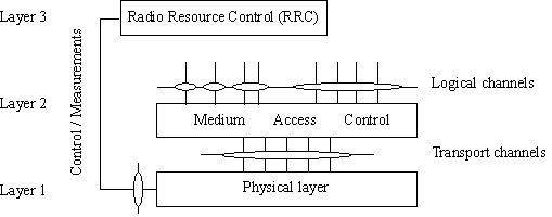
The radio interface is composed of the Layer 1, 2 and 3. Below figure shows the E-UTRA radio interface protocol architecture around the physical layer (Layer 1). The physical layer interfaces the Medium Access Control (MAC) sub-layer of Layer 2 and the Radio Resource Control (RRC) Layer of Layer 3. The circles between different layer/sub-layers indicate Service Access Points (SAPs). The physical layer offers a transport channel to MAC. The transport channel is characterized by how the information is transferred over the radio interface. MAC offers different logical channels to the Radio Link Control (RLC) sub-layer of Layer 2. A logical channel is characterized by the type of information transferred.


Service provided to higher layers

The physical layer offers data transport services to higher layers. The access to these services is through the use of a transport channel via the MAC sub-layer. The physical layer is expected to perform the following functions in order to provide the data transport service:

- Error detection on the transport channel and indication to higher layers
- FEC encoding/decoding of the transport channel
- Hybrid ARQ soft-combining
- Rate matching of the coded transport channel to physical channels
- Mapping of the coded transport channel onto physical channels
- Power weighting of physical channels
- Modulation and demodulation of physical channels
- Frequency and time synchronisation
- Radio characteristics measurements and indication to higher layers
- Multiple Input Multiple Output (MIMO) antenna processing
- Transmit Diversity (TX diversity)
- Beamforming
- RF processing.

Monday, September 20, 2010

SRVCC between LTE and 3GPP2 1xCS

Basics:
  • 1xCS: The 3GPP2 legacy circuit switched signalling system as defined in 3GPP2 X.S0042-0
  • 3GPP SRVCC UE: A 3GPP SRVCC UE is a UE enhanced for IMS Service Continuity with the additional UE capabilities such as SRVCC between E-UTRAN and 3GPP UTRAN and / or between E-UTRAN and 3GPP GERAN and / or between UTRAN (HSPA) and 3GPP UTRAN and 3GPP GERAN.
Concept:

For SRVCC-capable UEs, the call is always anchored at the VCC AS in the 3GPP2's IMS. The 3GPP2 1xCS IWS enables a single radio UE to communicate in parallel both with the source system and the target system. From VCC perspective, this mechanism minimizes the voice gap by supporting the transport of signalling for establishment of the target CS access leg while the terminal is connected to the source PS access network.
Transport of 3GPP2 1xCS signalling messages for preparation of the CS access leg in the target system

The S102 reference point is used to convey 3GPP2 1xCS signalling messages between the MME and 3GPP2 1xCS IWS. These 1x CS signalling messages are actually exchanged between the UE and the 3GPP2 1xCS IWS, and S102 is only one link in the overall UE 1xCS IWS tunnelling path. On the remaining portion of the tunnelling path, the 3GPP2 1xCS signalling messages are encapsulated in E UTRAN/EPS tunnelling messages (UE MME).

E-UTRAN and 3GPP2 1xCS SRVCC architecture


SRVCC architecture for E-UTRAN to 3GPP2 1xCS

Call flows for SRVCC from E-UTRAN

LTE VoIP-to-1x CS voice service continuity
1. Ongoing VoIP session over the IMS access leg established over EPS/E UTRAN access.

2. 1xCS SRVCC UE sends measurement reports to eNodeB.

3. The E UTRAN (e.g., based on some trigger, measurement reports) makes a determination to initiate an inter technology handover to cdma2000 1xRTT.

4. The E UTRAN signals the UE to perform an inter technology handover by sending a Handover from EUTRA Preparation Request message.

5. The UE initiates signalling for establishment of the CS access leg by sending a UL handover preparation Transfer message containing the 1xRTT Origination message. For the case of emergency voice service continuity, the request includes a Request-Type = "emergency handover" and in the case of UE operating in Limited Service Mode the MEID (e.g. IMEI) is included.

6. The E UTRAN sends an Uplink S1 cdma2000 Tunnelling (MEID, RAND, 1x Origination, Reference CellID) message to the MME. The eNodeB will also include CDMA2000 HO Required Indication IE to Uplink S1 CDMA2000 Tunnelling message, which indicates to the MME that the handover preparation has started.

7. Upon reception of the Uplink S1 cdma2000 Tunnelling message, the MME selects a 3GPP2 1xCS IWS based on Reference CellID and encapsulates the 1x Origination Message along with the MEID and RAND in a S102 Direct Transfer message (as "1x Air Interface Signalling").

8. The traffic channel resources are established in the 1x RTT system and 3GPP2 1xCS procedures for initiation of Session Transfer are performed as per 3GPP2 X.S0042 [4].

9. The 3GPP2 1xCS IWS creates a 1x message and encapsulates it in a S102 Direct Transfer message (1x message, Handover indicator). If the 3GPP2 access was able to allocate resources successfully, the 1x message is a 1x Handover Direction message and the handover indicator indicates successful resource allocation. Otherwise, the handover indicator indicates to the MME that handover preparation failed and the embedded 1x message indicates the failure to the UE.

10. The MME sends the 1x message and CDMA2000 HO Status IE in a Downlink S1 cdma2000 Tunnelling message to the E UTRAN. The CDMA2000 HO Status IE is set according to the handover indicator received over the S102 tunnel.

11. If the CDMA2000 HO Status IE indicates successful handover preparation, the E UTRAN forwards the 1x Handoff Direction message embedded in a Mobility from EUTRA Command message to the UE. This is perceived by the UE as a Handover Command message. If handover preparation failed, DL Information transfer message will be sent instead, with the embedded 1xRTT message that indicates the failure to the UE.

12. Once the UE receives the traffic channel information from the cdma2000 1xRTT system, the UE retunes to the 1xRTT radio access network and performs traffic channel acquisition with the 1xRTT CS access (e.g., 1xRTT BSS).

13. The UE sends a 1xRTT handoff completion message to the 1xRTT CS access (e.g., 1xRTT BSS).

14. The 1xRTT CS Access sends message to 1xRTT MSC to indicate of handoff done. The resources between 1x CS IWS and 1xRTT MSC may be released at this step.

15. Ongoing voice call over the CS access leg established over 1xRTT access. The E UTRAN/EPS context may be released based on the normal E UTRAN/EPS procedure.

16. The eNodeB sends an S1 UE Context Release Request (Cause) message to the MME. Cause indicates the S1 release procedure is caused by handover from E-UTRAN to 1xRTT.

17. The MME exchanges Suspend Request/ Acknowledge messages with the S GW / P GW. The S1-U bearers are released for all EPS bearers and the GBR bearers are deactivated by the MME. The non-GBR bearers are preserved and are marked as suspended in the S GW / P GW. Upon receipt of downlink data the S GW should not send a downlink data notification message to the MME.

18. S1 UE Context in the eNodeB is released as specified in TS 23.401 [2].

19. For an emergency services session after handover is complete, if the control plane location solution is used on the source side, the source MME shall send a Subscriber Location Report carrying an indication of the 1xRTT MSC (e.g. reference cell ID) to the GMLC associated with the source side to support location continuity. This enables location continuity for the 1xRTT side. Alternatively, if the control plane solution is not used on the source side, location continuity procedures shall be instigated on the 1xRTT side.